System description
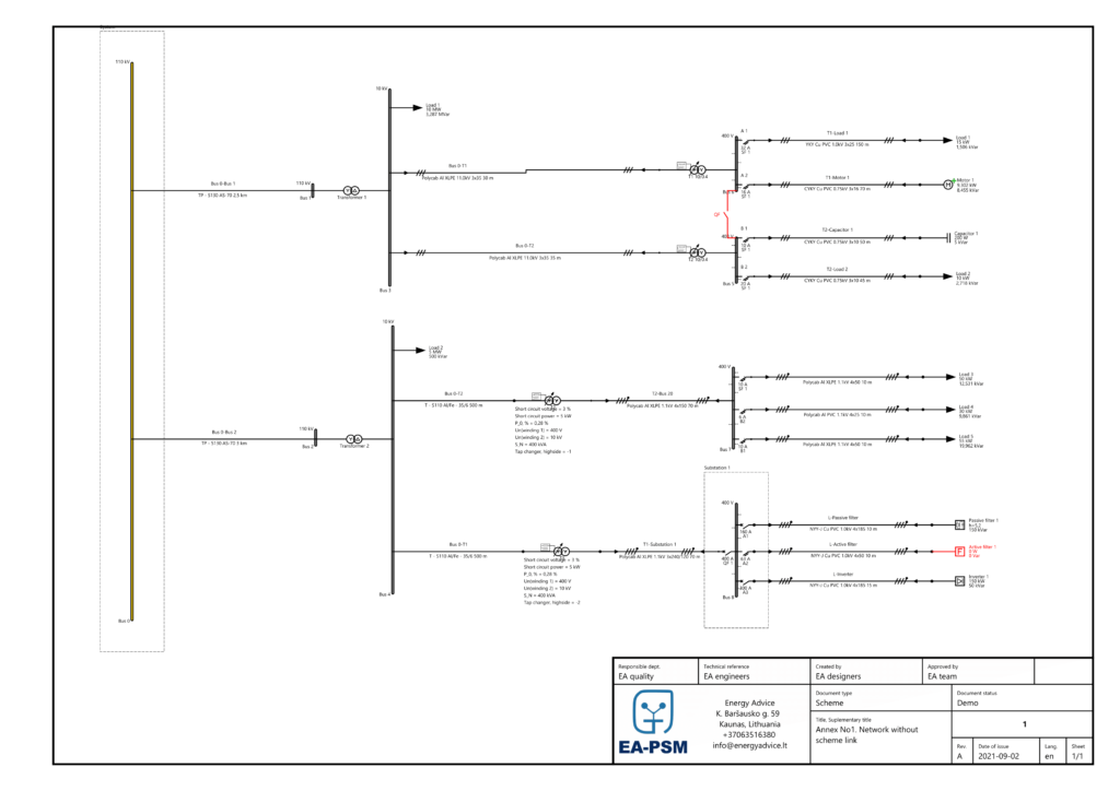
The detailed scheme and parameters of the analyzed network are depicted in Annex No. 1. at the bottom.
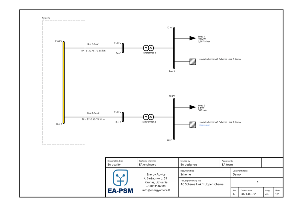
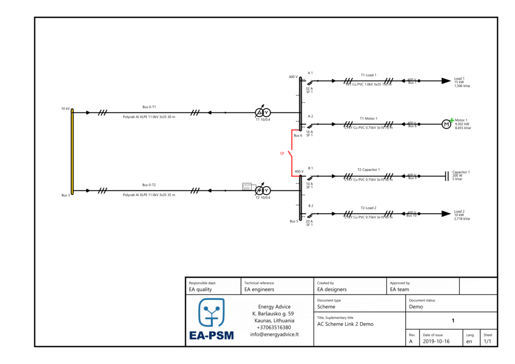
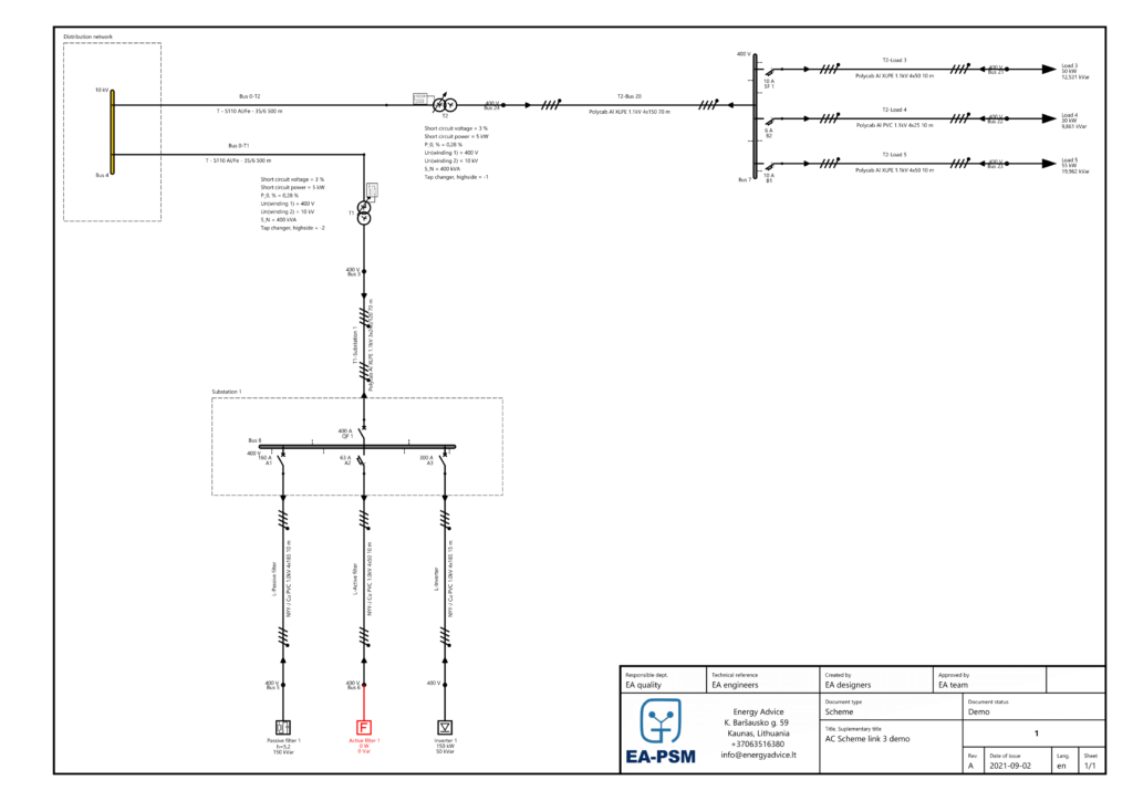
Two scenarios are analyzed: 1) the whole network is modeled at one scheme; 2) the network is divided and parts of the network are modeled as separate schemes. Schemes are linked to the base scheme using the scheme link feature.
One part of the network is linked as the line simply using the scheme link element (Scheme Link 1). This method is recommended if constant changes are performed at the linked scheme.
Another part of the network is linked as an equivalent motor using scheme element and calculating equivalent (Scheme Link 2). This method is recommended if the linked scheme is not being changed.
The difference between these methods is that while the first method performs calculations for both the upper and linked scheme at the same time, using the second method there is an equivalent calculated and calculations are performed at one scheme at a time.
Power flow calculations
Results of power flow calculations are depicted in Table 1. Results of a current, phasor, active and reactive power are presented and percental error is calculated.
The percental error shows that calculations using the Scheme link element can be considered reliable as the error in most cases is lower than 1 %. The higher error only appears when values of rather smaller amplitudes are compared. Thus, mathematically results in a higher percental error, although practically can still be considered a rather small error.
Table 1. Power flow calculation results and comparison

Short circuit calculations
Scheme link element is dedicated to dividing the scheme into logical blocks thus reducing graphics lag and creating the possibility to calculate equivalents.
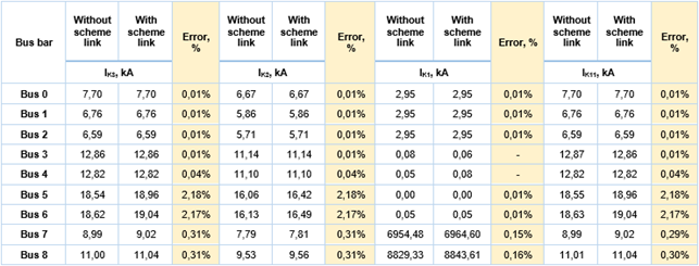
Short circuit calculations of K3 – three-phase short circuit; K2 – phase-to-phase short circuit; K1 – phase-to-earth short circuit; K1,1 – two-phase-to-earth short circuit were performed. Fault branch short circuit currents calculated at maximum and minimum conditions are presented in Table 2 and Table 3.
The percental error shows that short circuit calculations using the Scheme link element can be considered reliable as the error in most cases is close to 0 %. The higher error only appears when values of rather smaller amplitudes are compared. Thus, mathematically results in a higher percental error, although practically can still be considered a rather small and insignificant error.
Table 2. Short circuit calculation results and comparison (at system minimum)

Table 3. Short circuit calculation results and comparison (at system maximum)
Conclusions
Scheme link feature can be considered reliable, as calculation error using various scheme link methods in most cases is close to 0 %. Thus, the scheme link feature provides reliable results while reducing calculation time and improving user experience working with schemes of a larger scale.
Annex No. 1
Note that you can click on all the Figures to enlarge them.
Figure 1 Network without scheme link
Figure 2 AC Scheme link Upper scheme
Figure 3 AC Scheme link 2 Demo
Figure 4 AC Scheme link 3 Demo

