Solar Power Plant connection Feasibility study

This feasibility study carries out calculations needed to connect a solar power plant to a low voltage grid following IEC standards

Object description

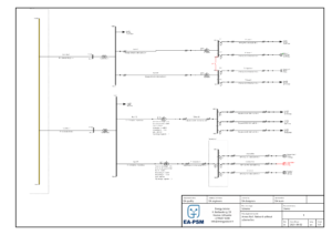
To connect a Photovoltaic system (PV system) to a low voltage (LV) grid a feasibility study was carried out following IEC standards. The study evaluates the connection of a 250 kW solar power plant to LV Section 2. The report example and the network’s single line diagram can be found in the downloadable pdf file down below. All the calculations were performed using EA-PSM Electric software. Learn more about the program. To learn how to conduct such studies in more detail join our hosted online webinar.

Distribution network short circuit currents

Short circuit currents calculations are based on IEC 60909 standard. Network data is depicted below:

short circuit current

Distribution network voltage is controlled with 110/10 kV autotransformers, they ensure that the voltage level is about 10.5 kV at the transformer terminals.

Equipment data

The main characteristics of transformers and low voltage cables are provided in the tables below.

transformer data
Transformer data
cable data
Cable data

AC cable selection

Cable ampacity

Firstly, in this study low voltage, AC cables for solar power plant inverters are selected. When connecting a PV system to the grid it is important to choose the cables according to the maximum output power of the inverter. The permitted currents for the cables are calculated as stated in IEC 60364-5-52 standard.

Maximum long term current from inverter: 250 kW -> 360 A

For 250 kW inverter 2(4×120) AL cables line is selected. Cable ampacity calculation results are depicted on the right.

Derated ampacity for AL 1(4×120) cable is 212 A. Therefore, 2 parallel cables must be used to ensure cable line capability in case of maximum long-term current. Two parallel cables will ensure 424 A line permitted current and about 17% safety margin. One step smaller cables line 2(4×95) would only allow 364 A maximum current, therefore, is not recommended due to the small safety margin.

cable ampacity
Voltage drop calculations

Voltage drop calculation results in the selected cable line are depicted below:

Voltage level solar power plant

The maximum voltage drop is equal to 2,493%. When the voltage in LV Section 2 bus is less than 107%, the voltage at solar inverter terminals will not exceed the permitted 10% overvoltage limit. Voltage calculation results with different transformer tap positions:
TAP = -1

Voltage level solar power plant

TAP = 0

Voltage level solar power plant

Calculation results show, that setting transformer tap changer position TAP = -1 or TAP = -2 should not be allowed.

Economic cable sizing

We will use the energy yield coefficient for inverter power derating to calculate annual power losses in the selected cable line. According to historical solar irradiation data, the energy yield coefficient is equal to 30%. Power losses calculation results with this energy yield coefficient are depicted below:

Voltage level solar power plant

Calculated average energy losses are equal to 500 W. Annual energy losses in cable lines are equal to 4380 kWh. The average electricity price is assumed to be 0.07 Eur/kWh. Annual financial losses due to power losses in the cable are equal to 306 Eur.


One step bigger cable line AL 2(4×150) would allow saving 876 kWh (61 Eur) per year, therefore, it is not economically beneficial to increase the cross-section area of the cable.

Grid Connection Feasibility Study

After selecting proper cables the grid connection feasibility study can be performed. In this study such calculations will be carried out:

  • Network Short Circuit Power
  • Voltage Calculation
  • Voltage Fluctuation
  • Harmonic Calculation
  • Load Flows Calculation
  • Short Circuit Current Calculation


Network Short Circuit Power
To begin the feasibility study network short circuit power will be evaluated. The power of the solar plant is 250 kW=0.25 MW. Medium voltage Section 2 calculated the maximum short circuit current is 16.676 kA. Network short circuit power is as follows:
short circuit power formula

The ratio between network short circuit power and solar plant power:

ratiot between short circuit power and solar pnat power

Because r < 0.1% power plant impact to voltage level and power quality in the distribution network is minimal and IEC 61000-3-7 standard does not limit the number of voltage changes.

Voltage calculation

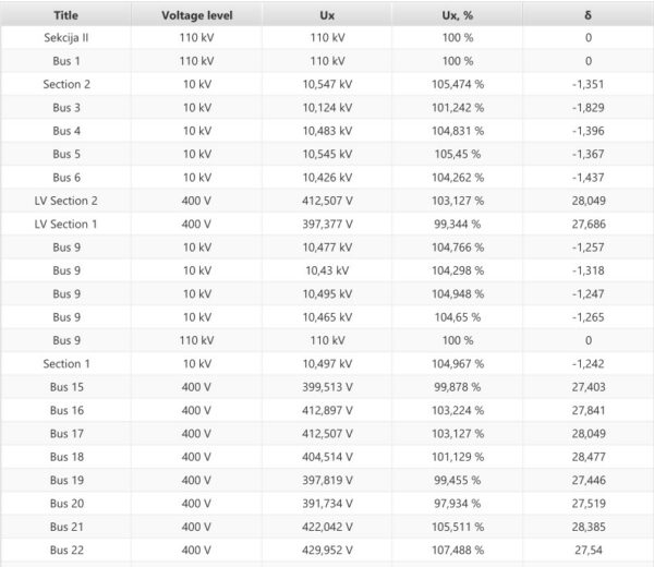
After determining short circuit power the voltage is evaluated. Let us estimate minimum loading conditions (all distribution network loads will consume 0% of their nominal power). When the solar power plant is working at full power, the voltage level at medium voltage Section 2 bus is equal to 10.503 kV (105.033%). Due to generation loss from the solar power plant, the voltage would go down to 10.502 kV (105.023%). As a result, the voltage difference is only 0.01%, therefore, the autotransformer will not change tap position.

Not only does the no-load operation mode must be determined but also the maximum loading conditions have to be evaluated (all distribution network loads will consume 100% from their nominal power). When the solar power plant is working at full power, the voltage at medium voltage Section 2 bus is equal to 10.548 kV (105.478%). Due to generation loss from the solar power plant, the voltage would go down to 10.547 kV (105.466%). As a result, the voltage difference is only 0.012%, therefore, the autotransformer will not change tap position.

In conclusion, power losses from the solar power plant’s effect on voltage levels in the distribution network are negligible.

Voltage fluctuation

Next voltage fluctuation will be analyzed. Voltage fluctuation coefficient is calculated according to IEC 61000-3-7 standard using the following formula:

voltage fluctuation formula

The maximum value of Pst2 (equal to 5.6) will be assumed in this calculation. Voltage difference d is calculated in the previous section (voltage level). The maximum voltage fluctuation coefficient is equal to:

votage fluctuation

According to IEC 61000-3-7 standard allowable Pst value is < 1. Therefore, the solar power plant will not cause voltage fluctuations.

Harmonics calculation

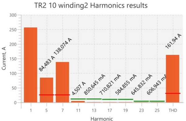
Let’s evaluate harmonic distortions next. Calculated current harmonics in TR2 10 are depicted in the graph below:

harmonic distortions caused by solar power plant

According to calculation results, we can see that the 5th and the 7th harmonics exceed IEEE 519 standard allowable limit. For this reason, we select the detuned passive harmonics filter. Reactor parameters for the filter are depicted below:

Filter data

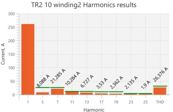
Harmonic results with the detuned reactor are depicted below:

harmonic distortions caused by solar power plant

After adding the filter, all harmonics are within permissible limits. The detuned filter is the cheapest option to reduce higher harmonics. Other possible alternatives are active filters and tuned passive filters.

Load flows calculation results (maximum load and generation conditions)

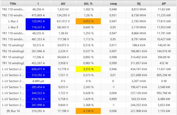
In addition to previously carried out, calculations load flows have to also be assessed. Results for the maximum load and generation conditions can be found in the tables below:

load flow calculation

The blue color indicates that the current exceeds recommended economical limit (1 mm² = 1 A).

Orange and yellow indicate a higher than recommended voltage drop in the cable.

Short circuit results

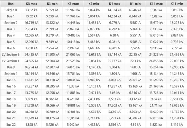
Finally, short circuit analysis is conducted. The result can be found in the table below. Types of short circuits:

  • K3 – three-phase short circuit;
  • K2 – phase-to-phase short circuit;
  • K1 – phase-to-earth short circuit;
  • K1,1 – two-phase-to-earth short circuit.
short circuit

Endnote

To learn how to carry out such a feasibility study in more detail join our hosted online webinar.

Downloadable PDF file

More to explore

We will send the demo to your email address

Are you interested
to read the whole post?

Fill out the given form to view the whole post

Confirm your email to get access to our news.