Directional overcurrent protection with EA-PSM

Complex double-end-fed and non-radial systems require directional protection equipment to maintain selectivity and proper tripping times

Introduction

Non – directional overcurrent protection is the most commonly used protection type. However, application of this type protection is limited to radial networks only. More complex double – end – fed and non – radial systems require directional protection equipment to maintain selectivity and acceptable tripping times. Example of the double – end – fed system is depicted in the picture below (Fig. 1).

EA-PSM Energy System Calculations software

Fig. 1 Double-end -fed system

For example, consider short circuit at SC1, that is depicted on the single line diagram. In this case, only “5” and “6” breakers should trip. To maintain this requirement, breaker “5” should trip before breaker “4” and breaker “6” should trip before breaker “7”. However, in case of SC2 short circuit, we want breaker “4” to trip before breaker “5”. Also, in case of SC3, we want breaker “7” to trip before breaker “6”. We can see that “SC3” and “SC2” requires opposite time settings than “SC1”. This example shows limitation of non-directional overcurrent protection equipment. However, if breakers “4”, “5”, “6” and “7” would be capable to sense current direction and have different tripping times for different faults, it would be possible to maintain selectivity even in this kind of network. And this is exactly what directional protection equipment does. To estimate current direction, it measures voltage and current and evaluates the phase difference between them. The main principle of tripping time and current direction settings is depicted at Fig. 2.

EA-PSM Energy System Calculations software

Fig. 2 Tripping time and current direction settings

In this case, if short circuit is at SC1, then breaker “5” will trip in 0,8 s and breaker “6” will trip in 1,0 s. Breaker “4” will not trip as it has 1,0s (>0,8s) time setting and breaker “7” will not trip as well, as it has 1,2s (>1,0s) time setting for relevant short circuit current. Also, if short circuit is at SC2, breaker “4” will trip before breaker “5” and breaker “3” will trip before breaker “2”. We can see, that this kind of protection logic can ensure selectivity even in double – end – fed system.

Implementing directional overcurrent protections in EA-PSM

User can implement directional overcurrent protections in EA-PSM. In this article we will describe the whole process of implementing directional overcurrent protections:

  1. For directional protection system to work properly, breakers should be added to both ends of each line in a double – end – fed or non – radial network. This is because in case of short circuit, current will always flow from two different directions.
  2. When breakers are added, open one of them (by double clicking on it) and in the breaker properties window go to “Protection” tab. Here select “Add Protection” button and add two overcurrent protection functions “I >” – one for each direction.
  3. In order to implement directional protection logic, user should select “Direction” from the drop-down menu that is highlighted in the picture 3.
EA-PSM Energy System Calculations software

Fig. 3 Protection device properties

Possible options for directional protection devices:

  • “Directional forward” – is direction from the breaker to the bus that is further from that breaker;
  • “Directional reverse” – is direction from the breaker to the bus that is closer to that breaker;
EA-PSM Energy System Calculations software

Fig. 4 Directional forward and directional reverse

  1. Set time ant current settings following the logic explained above. Current settings should be selected about 1,2 times higher than maximum load flow current to avoid false tripping.
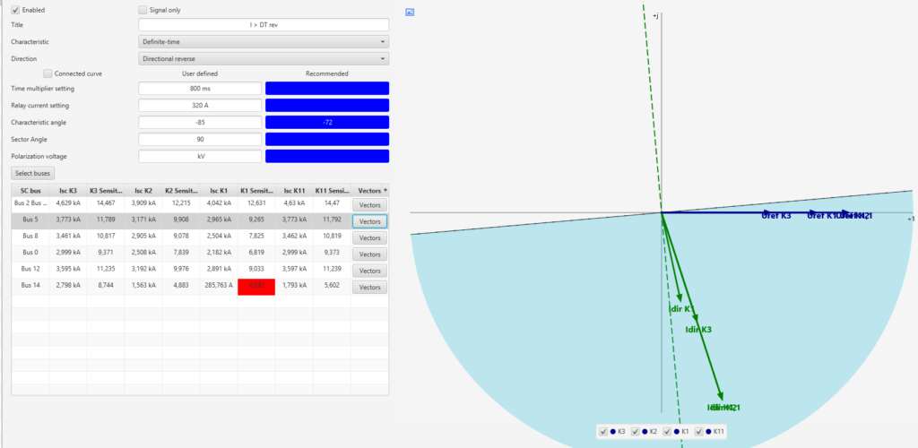
  2. Finally set “Voltage Sector” and “Characteristic angle”. The goal is to set these parameters so that each vector in the relevant direction will fit into the blue area as depicted below. Suitability of settings should be checked according to short circuit calculation results.

To evaluate resistance of busbars, connections and arc it is possible to calculate short circuit with fault resistance. To select fault resistance open Tools → Settings → Calculation → Short Circuit and set Rfault. Vector angles will depend on the selected Rfault, therefore, it is necessary to make sure that directional protection equipment will operate properly with high and low Rfault resistance.

To display vectors on the protection plot, select button “Vectors” next to the calculation results in the “Protection” tab. At the beginning, only the relevant direction short circuit results will be provided in the results table, however, user can add other short circuit results by pushing “Select buses”. This will allow to analyze opposite direction current vectors that should not be covered by the blue area. Also, it is possible to set Polarization voltage. This is a minimum voltage needed for the protection to operate.

EA-PSM Energy System Calculations software

Fig. 5 Protection vectors chart

Settings of protection devices from the analyzed example are depicted in Table 1. To get this table user should select “Summaries → Protection summary → Overcurrent”.

Table 1 Protection summary

EA-PSM Energy System Calculations software

When settings are specified, it is recommended to check protection operation with “Protection tracking” function. This function can be launched from the main EA-PSM window by selecting “Optimize → Protection tracking”.

After checking protection operation with K3, K2, K11, MIN and MAX short circuits with Rfault = 10 mOhms and Rfault = 10 Ohms results were generated as depicted at Table 2:

Table 2 Protection tracking results

EA-PSM Energy System Calculations software

From these results it is obvious that protections operate selectively. With K1 MIN and MAX results were generated as depicted at Table 3:

Table 3 Protection tracking results (K1)

EA-PSM Energy System Calculations software

In case of K1 short circuits in Bus 6 and Bus 14 protections where not tripping due to lack of sensitivity. Generator nominal current is about 820 A, while K1 MIN short circuit current from system at Bus 6 is only about 900 A with lowest Rfault setting. Therefore, ground fault protections should be used.

Conclusions

EA-PSM Electric provided functionality can be used to design and size directional overcurrent protection and track its tripping times.

More to explore

We will send the demo to your email address

Are you interested
to read the whole post?

Fill out the given form to view the whole post

Confirm your email to get access to our news.