
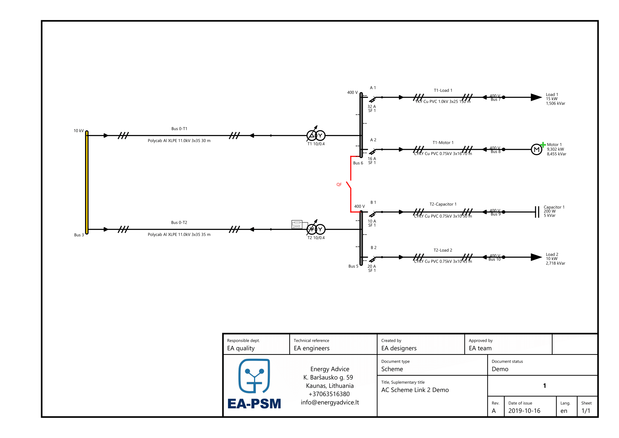

Before each new release of EA-PSM Electric, validation cases are prepared, thus ensuring new features are working properly. At this validation case, arc flash scenarios for three-phase medium voltage and low voltage systems according to the IEEE 1584-2018 standard are analysed.

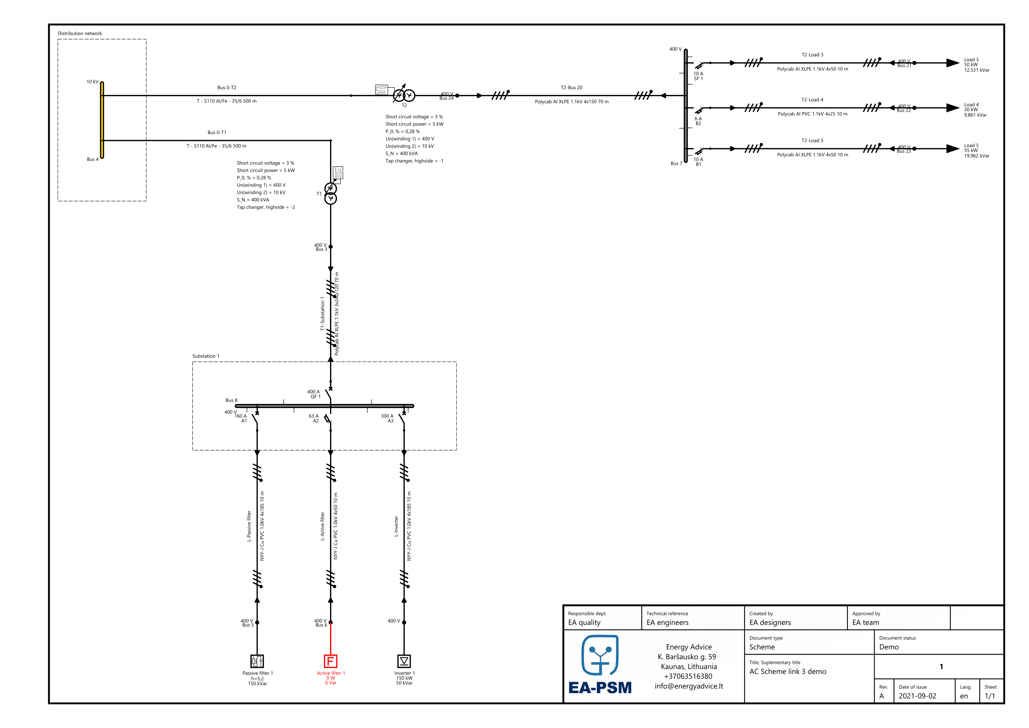
This feasibility study carries out calculations needed to connect a solar power plant to a low voltage grid following IEC standards